Lab 1: Microcontrollers

Baby steps, everyone!

Wanna know more?

Objective

This lab allowed us to gain familiarity with basic arduino functionality and setup. Furthermore, it was the first instance of interfacing the digital and physical in our robot.

In this lab, digital signals were produced (both on built in and through connect circuitry), analog signals were read and produced, and the robot and servos were assembled and driven for the first time.

Procedure

We split into 2 groups. Luke and Orby worked on the arduino testing sections of the lab and Orrin worked on building the robot. Once the robot was ready to be programed to move, Caitlin and Orby worked on the circuitry for the servos, Labhansh and Luke worked on the code.

Let's Break it Down

Understanding Arduinos

Blinking an internal LED

We used the 'Blink' sketch that came with the Arduino IDE in order to make the LED on the Arduino Uno blink. We found the Blink sketch in File > Examples > 1. Basics > Blink. The code for that skecth is below:

//the setup function runs once when you press reset or power the board
        void setup() {
          pinMode(LED_BUILTIN, OUTPUT);      // initialize internal LED pin as an output.
        }

        // the loop function runs over and over again forever
        void loop() {
          digitalWrite(LED_BUILTIN, HIGH);   // turn LED on by making voltage HIGH
          delay(1000);             // wait for a second
          digitalWrite(LED_BUILTIN, LOW);    // turn LED off by making the voltage LOW
          delay(1000);             // wait for a second
        }
        

Below is a video of the Internal LED blinking.

Blinking an external LED

In order for the 'Blink' code to work with an external LED, we replaced all occurrences of LED_BUILTIN in the original code with 0 which was the number of the digital pin we chose to write to.

//the setup function runs once when you press reset or power the board
        void setup() {
          pinMode(0, OUTPUT);      // initialize digital pin 0 as an output.
        }

        // the loop function runs over and over again forever
        void loop() {
          digitalWrite(0, HIGH);   // turn LED on by making voltage HIGH
          delay(1000);             // wait for a second
          digitalWrite(0, LOW);    // turn LED off by making the voltage LOW
          delay(1000);             // wait for a second
        }
        

Below is a video of the external LED blinking:

We repeated this procedure for all the other digital pins on the board to ensure that they worked.

Note: For this part, we connected a 300Ω resistor in series with everything we connected to a pin.

Analyzing Potentiometers

Reading the value of a potentiometer via the serial port

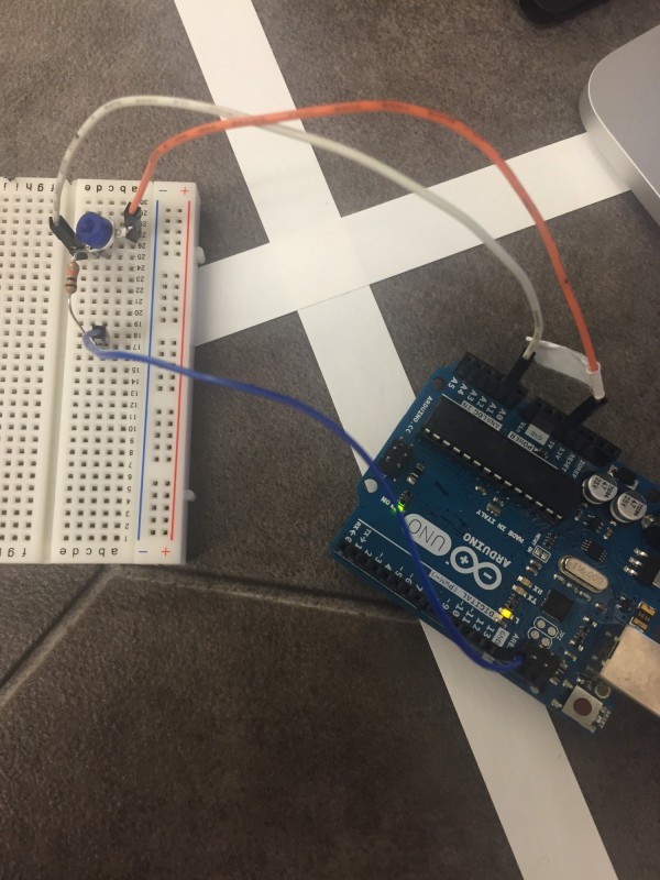
We connected the potentiometer to the Arduino Uno (using the circuit diagram shown below) as shown below:

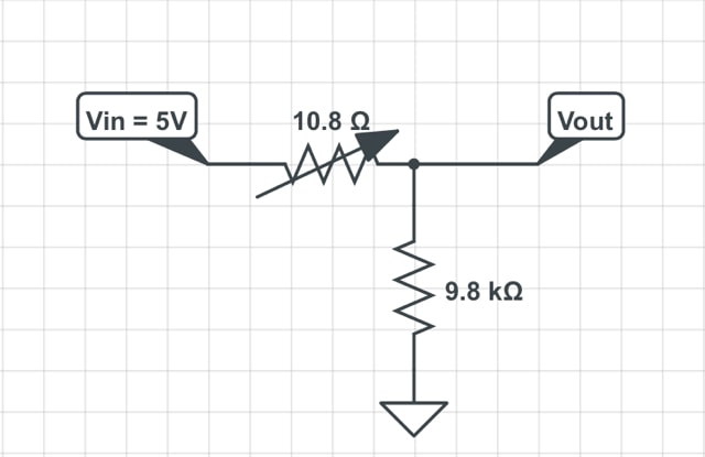
We then wrote code to initialise the serial connection (to enable us to print the analogue output to the serial port). We noticed that the value of the analogue output was between 0 and 1023 but we wanted the range to be 0 - 5 so we multiplied the value of the analogue output by 5/1023 which was 0.0049. We programmed it to print a value to the serial port every half second.

int analogPin = 1;     // potentiometer wiper (middle terminal) connected to analog pin 1
                               // outside leads to ground and +5V
        int val = 0;           // variable to store the value read

        void setup()
        {
          Serial.begin(9600);              //  setup serial
        }

        void loop()
        {
          val = analogRead(analogPin);     // read the input pin
          Serial.println(val*.0049);       // debug value 
          delay(500);                      // delay half-second
        }
        

Below is a video of the analogue output being read by the serial monitor:

Mapping the value of potentiometer to the LED

This is a simple extension of the above code for reading a potentiometer value. Notice that only one line was added at the end of the program: analogWrite(ledPin, map(val, 0, 1023, 0, 255));. The Arduino analogWrite reference page states that the write value must be between 0 and 255. Thus, we wrote this line that maps the potentiometer value to the necessary parameters (0 to 255), and writes this value to the LED pin. See the full code below:

int ledPin = 11;
        int analogPin = 5;     // potentiometer wiper (middle terminal) connected to analog pin 5
                               // outside leads to ground and +5V
        int val = 0;           // variable to store the value read

        void setup()
        {
          Serial.begin(9600);              //  setup serial
        }

        void loop()
        {
          val = analogRead(analogPin);     // read the input pin
          Serial.println(val*.0049);       // debug value
          delay(500);                      // delay half-second
          analogWrite(ledPin, map(val, 0, 1023, 0, 255));
        }
        

And below is a video demonstrating LED brightness controlled by potentiometer:

Mapping the value of potentiometer to the servo

Here, we want to be able to turn the potentiometer to control the direction and speed of the servo. Recall that the servo can be given values 0-180, where 0 is its fastest clockwise speed, 180 is the fastest counter-clockwise speed, and 91 is stationary.

We simply had to change the mapping line from 0-255 to 0-180. Notice in the video below that, while spinning the potentiometer from its one extreme to the other, the servo approaches its stationary point; it slows down, stops, and then starts spinning again in the opposite direction.

See below for a video demonstrating servo speed/direction controlled by potentiometer:

Assembling Arduino Schwarzenegger

Our robot was assembled in the classic “tri-pod” design with 2 wheels (attached to servos) and a ball bearing. The electronic hardware was stored on the top of the central chassis.

We used:

Once the first robot worked as required (moved in square), we changed the chassis to one where screwing down the 3 major components (Arduino board, bread board, power source), was possible. We will likely continue to alter the setup, however right now, balance was desired.

Learning to Drive

We looked up the library code for servos to determine how to make the robot move. We programed functions for each wheel after determining what speed we wanted. We then wrote a code that would move it in a square continuously whenever power was on. Here is our code.

#include <Servo.h>
                               // outside leads to ground and +5V
        Servo leftWheel, rightWheel;
        int leftWheelPin = 10, rightWheelPin = 11;
        void setup()
        {
          leftWheel.attach(leftWheelPin);
          rightWheel.attach(rightWheelPin);
          leftWheel.write(90);
          rightWheel.write(90);
        }

        void moveLeftWheelAntiClockwise()
        {
          leftWheel.write(120);
        }

        void moveLeftWheelClockwise()
        {
          leftWheel.write(60);
        }

        void moveRightWheelAntiClockwise()
        {
          rightWheel.write(120);
        }

        void moveRightWheelClockwise()
        {
          rightWheel.write(60);
        }

        void forward(int steps)
        {
          for(int i=0;i<steps;i++)
          {
            moveLeftWheelAntiClockwise();
            moveRightWheelClockwise();
          }  
        }

        void reverse(int steps)
        {
          for(int i=0;i<steps;i++)
          {
            moveLeftWheelClockwise();
            moveRightWheelAntiClockwise();
          }  
        }

        void stopRight()
        {
          rightWheel.write(90);
        }

        void stopLeft()
        {
          leftWheel.write(90);
        }

        void left()
        {
          for(int i=0;i<10;i++)
          {
            moveLeftWheelAntiClockwise();
          }  
        }

        void right()
        {
          for(int i=0;i<10;i++)
          {
            moveRightWheelClockwise();
          }  
        }


        void loop()
        {
          
          forward(10);
          delay(3000);
          stopLeft();
          delay(900);
          
        }
        

And here is it moving: