Lab 2: Analog Circuitry and FFTs

Sensory overload!

Wanna know more?

Objective

This lab began the process of adding various sensors and filters to analyze the world around our robot, specifically in terms of auditory and spatial awareness. In this lab, acoustic and IR signals were taken and read into a combination of sensors, filters, and amplifiers in order to detect them. Eventually, the detections of these external stimuli will lead to actions taken by the robot.

Procedure

There were two sections of the lab to be tackled: acoustic and optical. Orby, Labhansh, and Orrin worked on the acoustic subteam. Caitlin and Luke worked on the optical subteam. Once both individual sections of code and hardware were working, Luke and Labhansh merged the code snippets into a singular, functional file.

Let's Break it Down

Optical Subteam

Caitlin and Luke

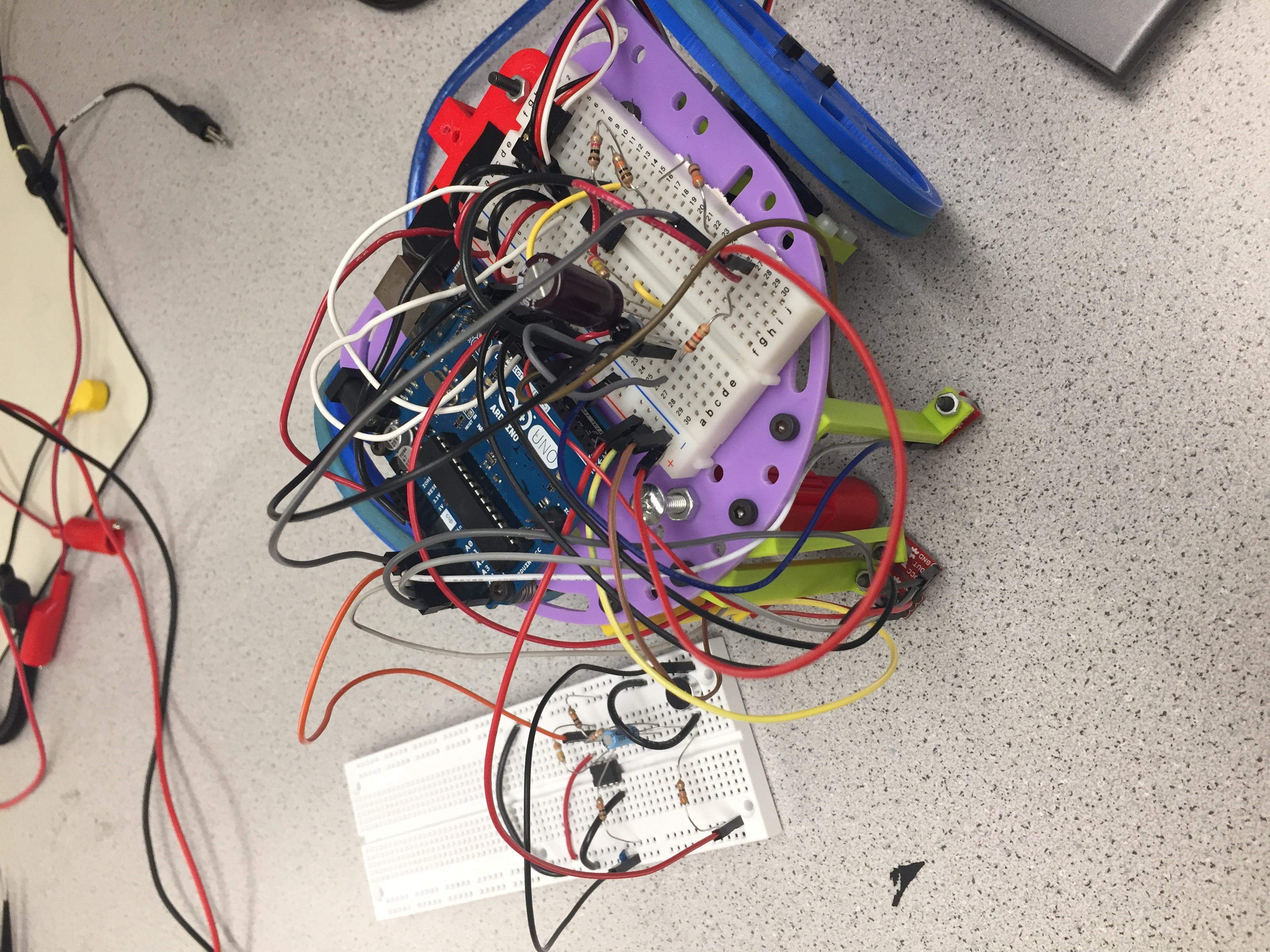
First, we created the phototransistor circuit on a breadboard and hooked the output up to our Arduino to test our use of the FFT library. Our ad-hoc procedure of testing the IR detection consisted of the following:

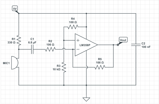
Observe the graph below of a successful detection of the target frequency of 6.08 kHz.

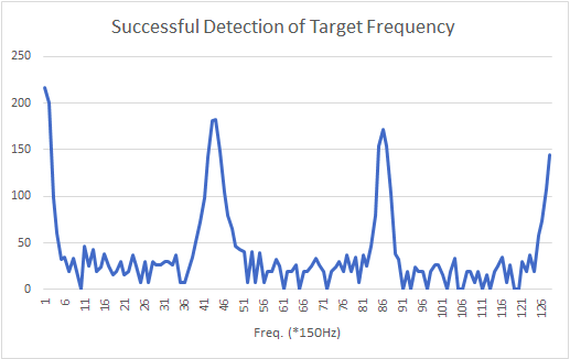
Notice how the value in bin ~43-44 spikes. This is our circuit detecting the target frequency! There are a total of 256 bins, the first 128 of which we examine, and each bin has a width of about 150 Hz, which we determined from the following data and calculations:

We noticed that our circuit detects the 6.08 kHz signal, but the peak appears in bins 43 or 44, which mathematically translates to about 6.4 kHz. With the bin width we calculated, one would expect 6.08 kHz to appear in bin 40 or 41. This error in bin location may be due to the actual clock speed being slower than 16 MHz, which is the ideal clock speed.

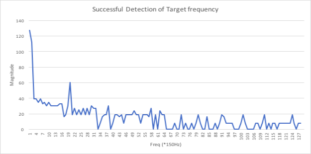
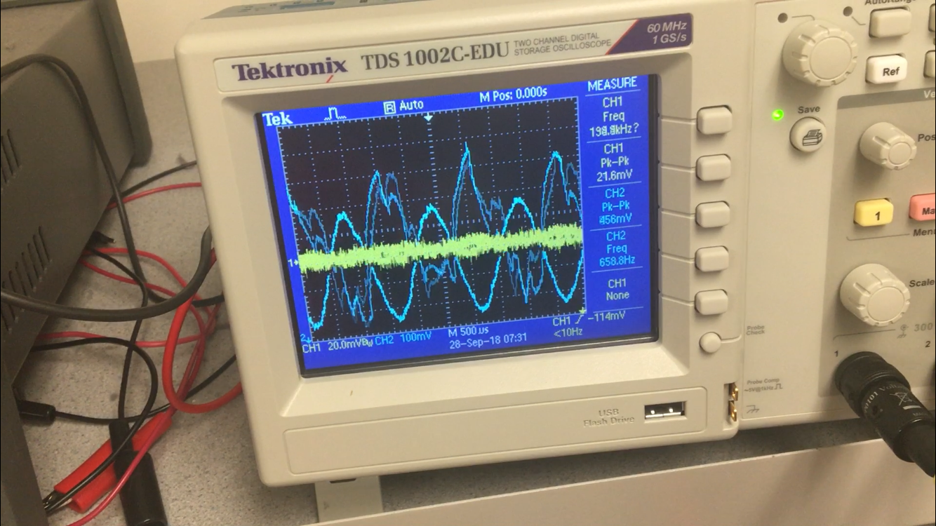
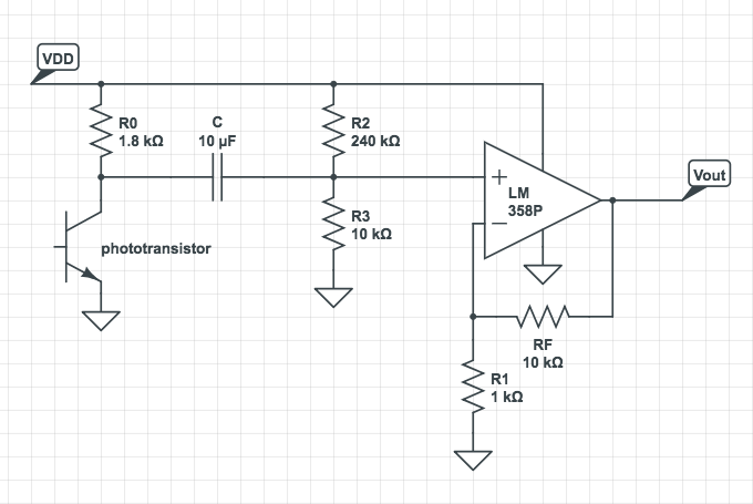
Now that we successfully detected the target frequency from a short distance, we needed to employ an amplifying circuit to allow us to detect from longer distances (~2 feet). Below is a diagram of our final optical circuit incorporating the LM358P non-inverting op-amp. It’s composed of a non-inverting amplifier and an accompanying circuit to reduce and control the input of DC voltage into the amplifier chip.

The non-inverting amplifier was designed to give a gain of 11 based on the following gain equation and resistor values: Av = 1 + RF/R1. Our RF resistor value was 10kΩ and our R1 resistor value was 1kΩ. The op-amp could only handle a maximum of 4V DC voltage, otherwise it would rail out, so the amount of DC voltage being inputted into the op-amp had to be regulated. We added a large capacitor, of capacitance 10μF, to block the DC voltage. If a DC voltage is applied across the capacitor, it will charge up, whereas if an alternating current (AC) is applied, the capacitor attempts to keep its voltage level constant, therefore letting current into the circuit.

To accompany the capacitor, we added a voltage divider so as to control the amount of DC voltage flowing into the amplifier chip and limit it to approximately 200mV, which, after the amplifier’s gain of 11, would maintain a DC voltage of approximately 2V, ensuring that the op-amp wouldn’t rail out. The resistor values for this voltage divider were calculated using Vout = Vin(R3/(R3+R2)) where Vout = 200mV and Vin = Vdd = 5V. R2 was found to be 24 times that of R3, so we used resistor values R2 = 240kΩ and R3 = 10kΩ.

A full diagram of the Optical circuit is below.

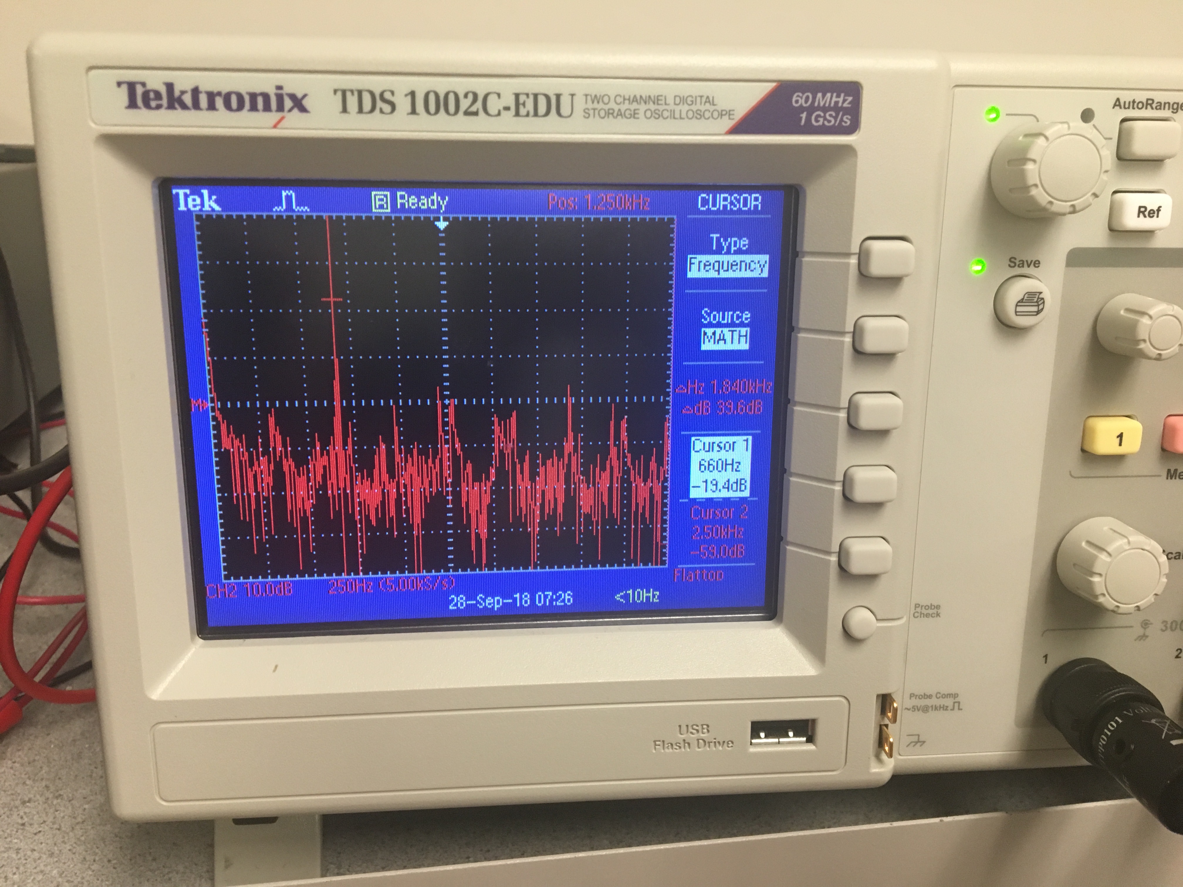
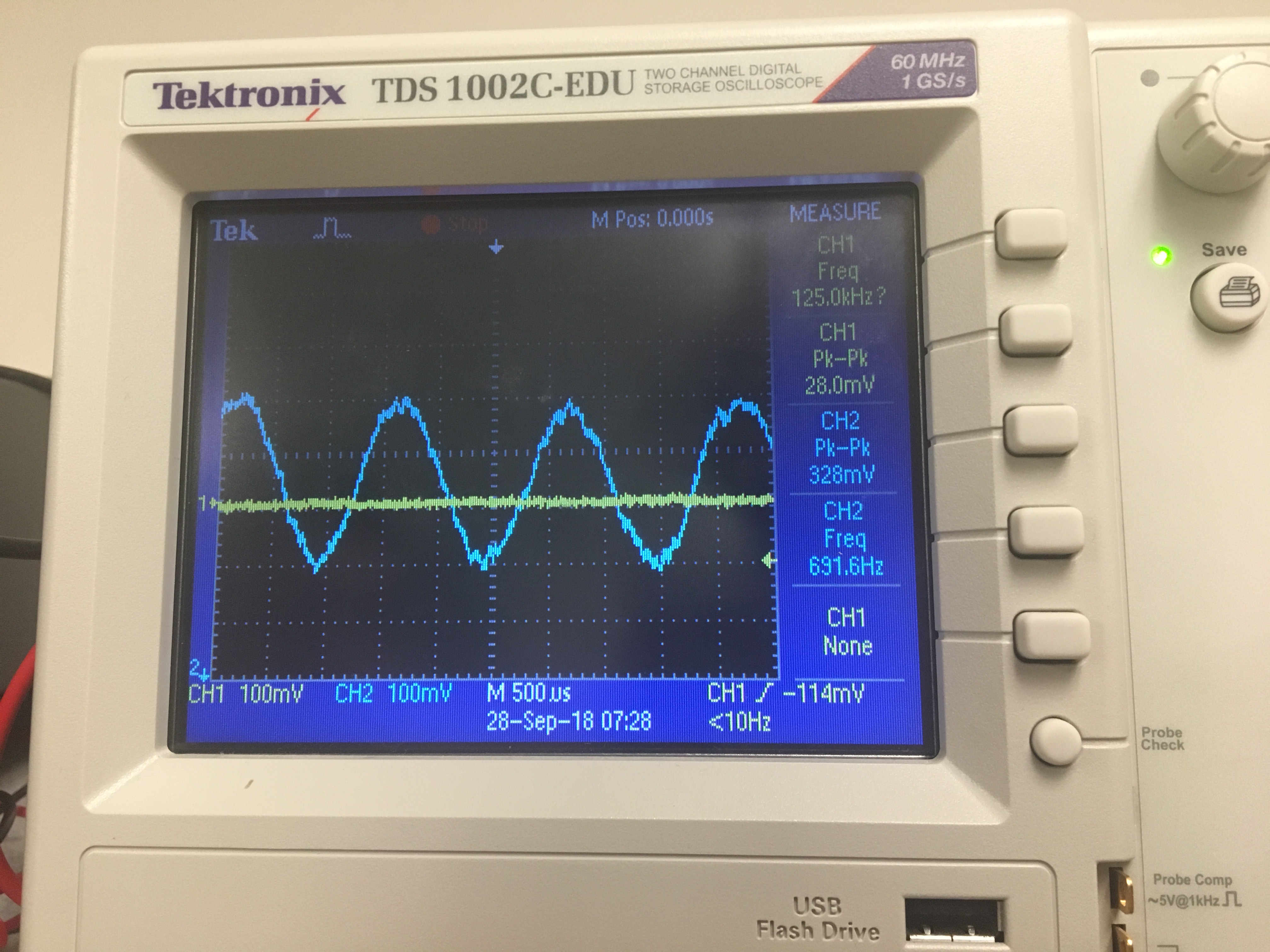
The whole point of this additional circuit was to amplify the output so as to make the signal detectable from a farther distance. The original gain of the amplifier circuit when it was simply a non-inverting amplifier is shown on the left. The final gain of the enture circuit, with the capacitor and voltage divider, is shown on the right.

Acoustic Subteam

Orrin, Orby, and Labhansh

We recognised that to make the acoustic part of this lab work, we would need to build an active band-pass filter. This would enable us to amplify all sounds at 660Hz. We built the following circuit to act as our active band-pass filter.

After building the circuit, we copied the FFT library into the 'libraries' folder of our Arduino IDE. We then modified the fft_adc_serial script to use analogRead() then attempted to run the fft_adc_serial script with the microphone. We ran into problems so we decided to test the circuit using the function generator.

We used the function generator to generate a frequency of 660 Hz with an amplitude of 30mV. The fft_adc_serial script runs at a frequency of 9600 Hz to collect 256 samples on each run. This means that each bin should have a width of 9600/256 = 37.5Hz. Since we were generating a 660 Hz tone, we expected the tone to be recognised around the 18th (660/37.5 = 17.6) bin.

From the graph below, it is clear that the tone was recognised between the 19th and 21st bin. We used these as our bin range when writing code. This error in bin location may be due fact that actual clock speed is a bit slower than the ideal clock speed.

We were able to obtain a gain of 11.7 using the function generator (as seen below). We were also able to successfully suppress sounds at all frequencies except harmonics of 660Hz. This is also shown below.

After ensuring this worked, we connected the microphone back into the circuit and got similar results (shown below). Our output sine waves weren't perfect but it was at the right frequency and we were able to see its general shape. Here, we had a gain of 21.1.

We added a line of code to display "We got 660Hz" when 660Hz was successfully detected.

Merged Code

Putting the pieces together!

Here’s a picture of Arduino Schwarzenegger with the Optical and Acoustic circuits attached. The Optical circuit is on the on-board breadboard, and the Acoustic is on the detached breadboard (for the time being).

Here is a snippet of our Optical code:

#define LOG_OUT 1 // use the log output function
        #define FFT_N 256 // set to 256 point fft

        #include <FFT.h> // include the library

        void setup() {
          Serial.begin(9600); // use the serial port
          TIMSK0 = 0; // turn off timer0 for lower jitter
          ADCSRA = 0xe5; // set the adc to free running mode
          ADMUX = 0x40; // use adc0
          DIDR0 = 0x01; // turn off the digital input for adc0
        }

        void loop() {
          while(1) { // reduces jitter
            cli();  // UDRE interrupt slows this way down on arduino1.0
            for (int i = 0 ; i < 512 ; i += 2) { // save 256 samples
              while(!(ADCSRA & 0x10)); // wait for adc to be ready
              ADCSRA = 0xf5; // restart adc
              byte m = ADCL; // fetch adc data
              byte j = ADCH;
              int k = (j << 8) | m; // form into an int
              k -= 0x0200; // form into a signed int
              k <<= 6; // form into a 16b signed int
              fft_input[i] = k; // put real data into even bins
              fft_input[i+1] = 0; // set odd bins to 0
            }
            fft_window(); // window the data for better frequency response
            fft_reorder(); // reorder the data before doing the fft
            fft_run(); // process the data in the fft
            fft_mag_log(); // take the output of the fft
            sei();
            if ( (fft_log_out[43] > 60) || (fft_log_out[44] > 60) ) {
              // do something! output a voltage to a pin to light an exterior LED
            }
            else {
              // write 0 voltage to the exterior LED
            }
            Serial.println("start");
            for (byte i = 0 ; i < FFT_N/2 ; i++) { 
              Serial.println(fft_log_out[i]); // send out the data
            }
          }
        }
        

And here is a snippet of our Acoustic code:

#define LOG_OUT 1 // use the log output function
        #define FFT_N 256 // set to 256 point fft

        #include <FFT.h> // include the library

        void setup() {
          Serial.begin(9600); // use the serial port
          TIMSK0 = 0; // turn off timer0 for lower jitter
          ADCSRA = 0xe5; // set the adc to free running mode
          ADMUX = 0x40; // use adc0
          DIDR0 = 0x01; // turn off the digital input for adc0
        }

        void loop() {
          while(1) { // reduces jitter
            cli();  // UDRE interrupt slows this way down on arduino1.0
            for (int i = 0 ; i < 512 ; i += 2) { // save 256 samples
              while(!(ADCSRA & 0x10)); // wait for adc to be ready
              ADCSRA = 0xf5; // restart adc
              byte m = ADCL; // fetch adc data
              byte j = ADCH;
              int k = (j << 8) | m; // form into an int
              k -= 0x0200; // form into a signed int
              k <<= 6; // form into a 16b signed int
              fft_input[i] = k; // put real data into even bins
              fft_input[i+1] = 0; // set odd bins to 0
            }
            fft_window(); // window the data for better frequency response
            fft_reorder(); // reorder the data before doing the fft
            fft_run(); // process the data in the fft
            fft_mag_log(); // take the output of the fft
            sei();
            if ( (fft_log_out[43] > 60) || (fft_log_out[44] > 60) ) {
              // do something! output a voltage to a pin to light an exterior LED
            }
            else {
              // write 0 voltage to the exterior LED
            }
            Serial.println("start");
            for (byte i = 0 ; i < FFT_N/2 ; i++) { 
              Serial.println(fft_log_out[i]); // send out the data
            }
          }
        }
        

Why are these programs different? Why does the Optical program assign so many register values, while the acoustic simply uses analogRead to monitor the microphone? The answer: analogRead cannot sample fast enough for 6 kHz. Instead of using analogRead, we assign a set of registers that are connected to the onboard ADC on the Uno. These control registers are linked to various controls such as ‘which pin to read from’, all of which is detailed in the ATmega328 datasheet. Note that these register values are also used in the Acoustic program, but they are not explicitly defined in our code; they are implicitly assigned default values. We will see how we preserve these values next.

To merge our two separate programs together without mixing up FFT data, we simply copy each segment (Acoustic and Optical) into a “toggling” conditional statement, i.e. the program would switch back and forth in executing the Acoustic FFT and the Optical FFT continuously. At the beginning of the Optical program, we save all of the register values that the Acoustic FFT uses, then assign our Optical-specified register values. At the end of the Optical segment, we re-assign the ‘old’ Acoustic register values back into the registers, so as to preserve the integrity of each program.

And here is a snippet of our Merged code:

#define LOG_OUT 1 // use the log output function
        #define FFT_N 256 // set to 256 point fft

        #include <FFT.h> // include the library

int old_TIMSK0, old_ADCSRA, old_ADMUX, old_DIDR0;

void setup() {
  Serial.begin(9600); // use the serial port
}

void loop() {
  Serial.println("start");
  bool toggle = true;
  while(1) {
    if(toggle)
    {
        cli();
        for (int i = 0 ; i < 512 ; i += 2) {
          fft_input[i] = analogRead(A1); // <-- NOTE THIS LINE
          fft_input[i+1] = 0;
        }
        fft_window();
        fft_reorder();
        fft_run();
        fft_mag_log();
        sei();
       
       if(fft_log_out[19] >= 45 || fft_log_out[20] >= 45 || fft_log_out[21] >= 45)
       {
            Serial.println("We got 660 Hz");
       }
    }
    else
    {
        // Store old values
        old_TIMSK0 = TIMSK0;
        old_ADCSRA = ADCSRA;
        old_ADMUX = ADMUX;
        old_DIDR0 = DIDR0;

        //Setup
        TIMSK0 = 0; // turn off timer0 for lower jitter
        ADCSRA = 0xe5; // set the adc to free running mode
        ADMUX = 0x40; // use adc0
        DIDR0 = 0x01; // turn off the digital input for adc0

        // Check
        cli();  // UDRE interrupt slows this way down on arduino1.0
        for (int i = 0 ; i < 512 ; i += 2) { // save 256 samples
              while(!(ADCSRA & 0x10)); // wait for adc to be ready
              ADCSRA = 0xf5; // restart adc
              byte m = ADCL; // fetch adc data
              byte j = ADCH;
              int k = (j << 8) | m; // form into an int
              k -= 0x0200; // form into a signed int
              k <<= 6; // form into a 16b signed int
              fft_input[i] = k; // put real data into even bins
              fft_input[i+1] = 0; // set odd bins to 0
        }
        fft_window(); // window the data for better frequency response
        fft_reorder(); // reorder the data before doing the fft
        fft_run(); // process the data in the fft
        fft_mag_log(); // take the output of the fft
        sei();
        if ( (fft_log_out[43] >= 60) || (fft_log_out[44] >= 60) ) {
              Serial.println("We got 6 kHz");
        }

        // Restore old values
        TIMSK0 = old_TIMSK0;
        ADCSRA = old_ADCSRA;
        ADMUX = old_ADMUX;
        DIDR0 = old_DIDR0;
    }
    toggle = !toggle;
  }
}

And here’s a video of Arduino Schwarzenegger running this merged code, and detecting both the 6 kHz IR and the 660 Hz sound!