GUI Interaction
Seeing is Believing
The GUI provided by the lab handout was relatively simple to use. After downloading the relevant files, all that was need to do to run the GUI was a simple python command: python main.py . Running this command would open a browser window with a GUI configured to the number of rows and columns given.
In order to update the interface, there were certain variables that could be declared:
- iamhere
- west
- north
- east
- south
- robot
- tshape
- tcolor
These variables represent the current location of the robot, the presence of walls, the detection of a robot nearby, and the existence of treasures with specific shapes and colors. This data was also passed along with integers representing x and y coordinates, similar to the statement 2,3,west=false,north=true,south=false, which defined the robot to be at coordinate location (2,3) with a wall to the north, not to the west or south.
To start with updating the GUI, the most simple and effective way to see if the values were being updated was through changing the x and y coordinates of the virtual robot. Information from the base station is sent with a simple Serial.println statement, so global variables to store incrementing x and y values were created and placed in a Serial.println statement within the GettingStarted.ino code provided to run the radio. The python command was then run (after ensuring that the serial monitor wasn’t running, otherwise it would be using the same port that the GUI would want to receive information from) and the GUI displayed. A video of this is below:
Because we are only allowed to use a restricted number of bits and we have a lot of data to transmit, we came up with the following data scheme to efficiently transmit the information.
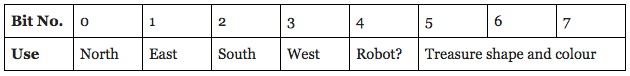
The three bits for treasure detection will be used as follows:
- 000: Blue square
- 001: Blue triangle
- 010: Blue diamond
- 011: Red square
- 100: Red triangle
- 101: Red diamond
To send this information between two radios connected to two separate boards, the roles of each radio had to be defined. There are two possible roles: transmitter, responsible for sending out data; and receiver, responsible for taking in data. The default role for all radios is to be a receiver, but the role could be switched by inputting ‘T’ or ‘R’ in the serial monitor to flip to transmitter or receiver, respectively.
The GettingStarted.ino code has, within the loop function, conditionals to handle what to do if the radio is in transmitter mode versus receiver mode. Both modes incorporate the movement of data, checking to make sure the transmission was sent/received, and sending an acknowledgement signal to the other radio.
The data needed to be transmitted between the two Arduinos is in regards to the location, orientation, and spatial awareness of the robot, as described above. Some of these variables, specifically the coordinates, cardinal direction, and surrounding walls, needed to be updated and maintained within the motion of the robot itself. We created a helper function called create_transmission to create the data to be transmitted to the receiver using the data scheme above. This helper function is shown below:
byte create_transmission(bool north=false,  bool east=false, bool south=false, bool west=false, bool robot_detected=false) {
        byte result = 0b00000000;
        byte tmp = 0b00000000;
        if (north) {
          tmp = 1 << 7;
          result = result | tmp;
        }
        if (east) {
          tmp = 1 << 6;
          result = result | tmp;
        }
        if (south) {
          tmp = 1 << 5;
          result = result | tmp;
        }
        if (west) {
          tmp = 1 << 4;
          result = result | tmp;
        }
        if (robot_detected) {
          tmp = 1 << 3;
          result = result | tmp;
        }
        return result;
      }
At first, to check that transmissions from the transmitter radio were appropriately received by the base station, we hardcoded values for x, y, and data to be sent. The video below shows the GUI responding to these new values and displaying the robot at a new place in the maze:
In order to simulate robot movement, we created a counter variable and three arrays: data_array, x_array and y_array.
We then stored values in these arrays according to the movement we wanted to simulate. Within the loop function, if the radio was transmitting, we looped over the values in each of the arrays, obtaining and transmitting values of x, y and data (from their respective arrays) as well as incrementing the value of the counter variable after each iteration. On the other hand, if the radio was receiving, we printed an API acceptable string to the GUI. This was done using a helper function create_gui_string which takes in a 3 element array and uses various conditionals to return an API acceptable string.
String create_gui_string(byte data[3]) {
        String result = "";
        //adding x, y
        result = String(data[0]) + "," + String(data[1]);
        //decoding existence of walls and other robots
        byte tmp = 0b00000000;
        if ((data[2] & (1 << 7)) != tmp) {
          result = result + ",north=true";
        }
        if ((data[2] & (1 << 6)) != tmp) {
          result = result + ",east=true";
        }
        if ((data[2] & (1 << 5)) != tmp) {
          result = result + ",south=true";
        }
        if ((data[2] & (1 << 4)) != tmp) {
          result = result + ",west=true";
        }
        if ((data[2] & (1 << 3)) != tmp) {
          result = result + ",robot=true";
        }
        return result;
      }
For the simulation of our robot's actual movements on the GUI, the following code was written and integrated within our general Arduino file:
The code snippets below outline the procedure used to appropriately update the values for these variables.
The definition of the global variables//variables for GUI---used to determine location/direction of robot---- int x = 0; int y = 0; int dir = 0; //0 --> relative north //1 --> relative east //2 --> relative south //3 --> relative west bool north = false; //existence of north wall (in front) bool south = false; //existence of south wall (behind) bool east = false; //existence of east wall (left) bool west = false; //existence of west wall (right)
// Orienting Functions ----------------------------------------
      // Used to determine coordinate location and cardinal direction of robot
      void orient_right_turn() {
        if (dir < 3) {
          dir = dir + 1;
        } else if (dir == 3) {
          dir = 0;
        }
      }

      void orient_left_turn() {
        if (dir > 0) {
          dir = dir - 1;
        } else if (dir == 0) {
          dir = 3;
        }
      }

      void orient_turn_around() {
        if (dir  == 0) {
          dir = 2;
        } else if (dir == 1) {
          dir = 3;
        } else if (dir == 2) {
          dir = 0;
        } else if (dir == 3) {
          dir = 1;
        }
      }
case FOLLOW_WALL:{
            bool atIntersection = isWhite(backLeft) && isWhite(backRight);
            if (atIntersection) {
              if (dir == 0) {
                north = frontWall();
                east = rightWall();
                west = leftWall();
                south = false;
                y = y + 1;
              }
              if (dir == 1) {
                north = leftWall();
                east = frontWall();
                west = false;
                south = rightWall();
                x = x + 1;
              }
              if (dir == 2) {
                north = false;
                east = leftWall();
                west = rightWall();
                south = frontWall();
                y = y - 1;
              }
              if (dir == 3) {
                north = rightWall();
                east = false;
                west = frontWall();
                south = leftWall();
                x = x - 1;
              }
              create_transmission(x,y,data);
            }
Speedbumps
There were a few...
The problems started with hardware issues. The second Arduino we were given wasn’t a real Arduino, and thus didn’t send the 3.3V to the radio that it needed to operate adequately. Once this issue was spotted, the radio then had to be hooked up to a direct power supply of 3.3V.
The easiest way to spot that a radio wasn’t working was to look at the addresses it displayed when the serial monitor was first opened. We hardcoded the message channels as 0x000000002CLL and 0x000000002DLL, so those were the values expected. However, there were issues where the address displayed would be 0x0000000000, even with the radios correctly powered and all of the pins on the radio, adaptor, and board probed for shorts and correct voltages.
The solution was often to re-upload the code to the board, open the serial monitor, and hope that the addresses were correct. There didn’t seem to be any reasoning as to when the radio would decide to not take in the correct message channel addresses, and similarly code, leading to hours spent attempting to pinpoint the problem only to have it work again after re-compiling the same files, with no edits having been made.
After struggling with the radio chip for a while, we decided to borrow one from another team. We then discovered that even though the radio chip was faulty, our code was also problematic. For some reason, it would only send data between the Arduinos two times before stopping as opposed to continuing to send data. The video below demonstrates the outputs on the serial monitor that we would see when we would run into this issue.
To figure out the cause of this problem, we added println statements after every while loop and if-else statement. By observing the outputs to the serial monitor, we were able to figure out that the cause of this problem was that one of the variables in the stopping condition of a while loop was being wrongly set in the body of the while loop. We were unable to figure out why the current variable assignment would be a problem before the end of the lab session.