For this lab, we used an FPGA ( a DE0-Nano board), an Arduino, and an OV7670 camera, to create a system that distinguishes red and blue color. The FPGA is used to clock the camera and read from the camera’s byte output, and transform said output into data that can be stored in memory and displayed on a screen. The Arduino is used to write register data to the camera and receive color detection information from the FPGA.
Procedure
The main goal in Lab 4 was to get the camera up and running and have our system distinguish between red and blue color, as well as communicate whether a treasure even exists. Although our live camera feed is still quite imperfect (this will likely cause problems for shape-detection further down the road), our system does indeed successfully meet this overarching goal of distinguishing color. The steps we took to complete this task are outlined below:
Create a Phase-Locked-Loop to ensure that the several clocks we require (the OV7670 requires a 24-MHz clock, the VGA module requires a 25-MHz clock, etc.) are treated in the FPGA as actual clock lines and that they are not skewed
On the Arduino:
Determine the register values needed to be written to their specific register addresses (using the OV7670 datasheet)
Write these register values to the camera via the Arduino (and a sketch file)
Successfully reading color data sent from the FPGA
On the FPGA:
Correctly display memory contents of an FPGA onto a screen
Correctly parse camera information (in our case, RGB-565-formatted data), and display it to the screen
Accurately determine if most pixels from the camera feed are red/blue (distinguishing color), and correctly sending such data
Integration:
Wiring the Arduino, Camera, and FPGA all together correctly such that the FPGA can successfully communicate color distinguishment to the Arduino
There are multiple clocks of different frequencies needed in our system; in order to lock them all together we initialized a phased- locked- loop (this ensures that there is minimal clock skew in our system). We created another file with an overall clock at 50 MHz. We then initialized each of our output clocks at 24, 25, and 50 MHz with 50% duty cycles. We then assigned an output pin for the 24 MHz clock (to be wired to the camera).
Arduino Side
Registers
The registers we write to are described in the following table:
Register
Address
Value
Purpose
COM7
0x12
0x80
Resets all registers to default values
COM3
0x0C
0x08
Enables scaling
CLKRC
0x11
0xC0
Enables ‘double-clocking’ and tells camera to use external clock
COM15
0x40
0xD0
Set output resolution to RGB-565
COM7
0x12
0x0E, 0x0C
QCIF format, and Color bar test enable, QCIF format, and Color bar test disable
COM17
0x42
0x08, 0x00
Enable color bar test, Disable color bar test
MVFP
0x1E
0x30
Flip and mirror the image
Again, these values were determined by looking through the OV7670 data sheet.
Writing Register Values from Arduino
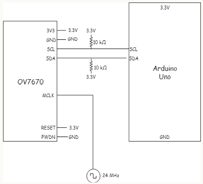
The wiring for the camera-Arduino is shown in the following picture:
Note: On the camera, the pins SIOC and SIOD correspond to SCL and SDA respectively.
Receiving FPGA data
We initialized 2 output pins in our Verilog code that would carry either 00 (neither), 01 (blue), or 10 (red). We then analyzed the output of the image processor (the RESULT variable) by linking each bit with an LED on the FPGA and examining which LEDs were lit. We used the LEDs to test whether our image processor worked, before hooking these pins from the FPGA up to the Arduino. The two pins were then directly connected into digital input pins on the Arduino with their variables initialized in the code. In order to show the code worked, we held a color test image up to the camera and then had the code print out whether it was red or blue. This function is relatively simple (just reading certain digital pins and outputting to serial monitor accordingly), and will be left off for brevity.
See a video of the FPGA sending color data to the Arduino:
FPGA Side
Displaying M9K memory contents
One of our initial tasks was to write a pattern directly into the FPGA memory and display it on the screen. We created an always block that updated on the positive edge of the 25MHz clock, that would enable memory writing if the X and Y addresses were inside the picture frame. We then wrote in colors directly into the pixel_data_RGB332 variable which would then be stored in the current address in memory, depending on whether they were in the range for the shape we wanted to create. The X and Y write addresses were subsequently changed as long as they were still within the screen width and height.
We successfully outputted our test pattern (a simple/arbitrary cross) as you can see below:
Down-sampler: color bar and camera feed
The downsampler takes the RGB 565 format image from the camera and then turns it into 8 bits that can be stored in our memory. RGB 565 format for pixels means one pixel equates to two bytes of information (first 5 pixels red, next 3 green, then next 3 green last 5 blue). We essentially parse the 565 data into 332 data by selecting the most significant digits for each color and enter them into the 8 bit 332 format.
When the camera V_Sync signal is high, this signals the end of an entire frame, so we reset the X and Y addresses. When V_Sync is low, and HREF was high, pixel data is transmitted row by row. Since the RGB 565 pixel data comes in bytes, and each pixel is two bytes of 565 data, we have to read across two clock cycles (of PCLK, outputted from the camera) to get the full info of one pixel. We use an auxiliary variable to keep track of which pixel (first or second) we are receiving, and store the camera input data in a register. When HREF is low again, the row is over and the Y address updates (we move down a row).
Here is our down-sampler code:
//Down-sampleralways @ ( posedgeP_CLOCK ) beginif ( old_vsync ==0&&V_SYNC==1 )begin// V_SYNC marks the end of// a frame: reset X and Y.W_EN<=0; // Don't write to memory!X_ADDR<=15'd0;
Y_ADDR<=15'd0;
i <=0;
endelseif ((HREF==0) && (old_href ==1)) begin// End of Row.W_EN<=0; // Don't write anything here!!X_ADDR<=15'd0; // Beginning of next rowY_ADDR<=Y_ADDR+15'd1; // Move down to next row
i <=0;
endelsebeginY_ADDR<=Y_ADDR;
if (HREF==1) beginif (i ==0)begin// First byte received of two.//(Blue info)W_EN<=0; // DON'T WRITE TO// MEMORY YET!
temp[7:0] <= CameraInput[7:0];
// Save blue info!
i <=1;
X_ADDR<=X_ADDR;
endelse// i = 1 : second byte!// (Red & Green info)begin
pixel_data_RGB332[7:5] <= CameraInput[7:5];
// Red
pixel_data_RGB332[4:2] <= CameraInput[2:0];
// Green
pixel_data_RGB332[1:0] <= temp[4:3];
// Blue// Now the pixel is finished! Update// WRITE_ADDRESS and enable memory writingW_EN<=1; // Memory is written.X_ADDR<=X_ADDR+15'd1; // Update X
i <=0;
endendelsebeginX_ADDR<=0;
i <=0;
endend
old_vsync =V_SYNC;
old_href =HREF;
end
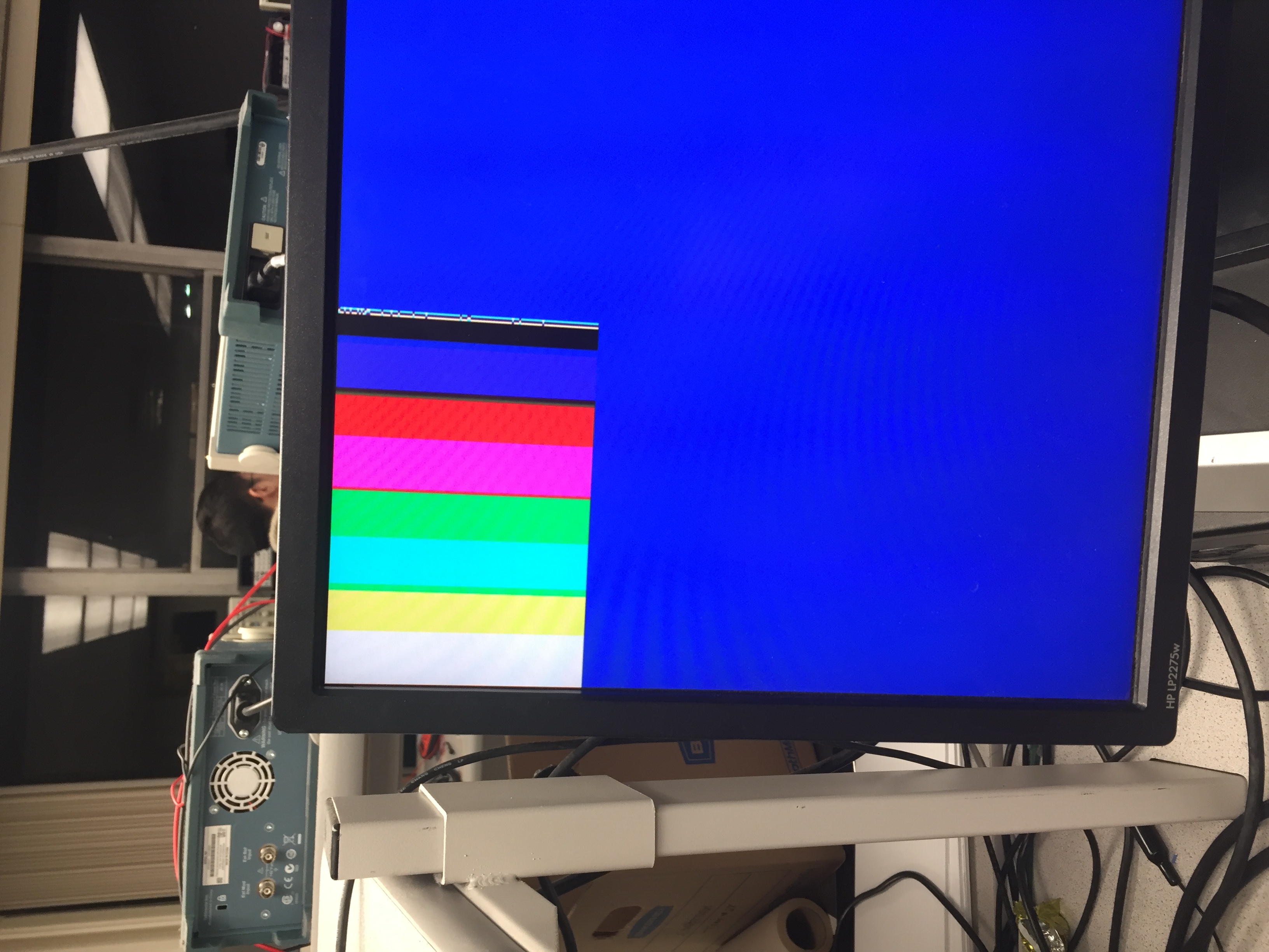
In order to test that the correct colors were being constructed after the downsampling, we updated the registers in the Arduino code to show a color bar and then checked to see that the correct colors were shown. Below is a picture of the color bar test:
We had trouble getting a consistent camera feed. While we managed to get reasonable colors and defined shapes, our video seemed to update in bars, which was best described as “flickering”. Despite looking through our code many times, analyzing the clocks, replacing all the hardware, and rewiring at least once, we were unable to get a clean image unless the gain was turned very low, at which point the feed was very dark.
Here is a video of this raw, imperfect camera feed:
However, after playing around with some more camera registers, we were able to obtain a relatively clean output. This is the register that alters the gain ceiling, which makes the image very dark, but smoothes out the camera feed. We added the following register to our list of registers to write in the Arduino file:
Register: COM9
Address: 0x14
Value: 0x0A
Purpose: After the gain ceiling
And here is a video of the clean feed:
Color Distinguishment
We wrote the image processor module to identify what was the dominant color of the camera's current frame. We created registers which update each time the RGB pixels from the downsampler with the color that is the largest in those bits. At the end of a frame, the totals are compared and the output RESULT is assigned to either 9’b01 if blue or 9’b10 if red, before all the variables are reset.
To test the image processor we assigned LEDs on the FPGA to light up according to which color was observed by the camera (as described in Arduino-Side, 3. Receiving FPGA data).
Here is our image-processor (color-detection) code:
always @ ( posedgeCLK ) begin// If we've reached the end of a frame, compare red and blue, and// output accordingly.// red = RESULT[1] high, and blue = RESULT[0] highif (VGA_VSYNC_NEG) begin// REDif ( redcounter > bluecounter ) begin
res =9'b10;
end// BLUEelseif ( redcounter < bluecounter ) begin
res =9'b01;
end// NEITHERelsebegin
res =9'b00;
end
red =0;
blue =0;
end// Mid-frame, increment red and blueelsebegin// Increment Redif ( ( PIXEL_IN[7:6] >PIXEL_IN[1:0] ) && ( PIXEL_IN[7:6] >2'b10 ) ) begin
red = red +1;
end// Increment Blueif ( ( PIXEL_IN[1:0] >PIXEL_IN[7:6] ) /*&& ( PIXEL_IN[1:0] > PIXEL_IN[4:3] ) */) begin
blue = blue +1;
end
redcounter = red;
bluecounter = blue;
endend
And here is a video of the full color detection system (referred in section Arduino-Side, 3. Receiving FPGA Data):
Note that our FPGA’s 2-bit treasure signal implicitly signifies whether or not there is a treasure (i.e. 00 = no treasure, 01 = blue treasure, 10 = red treasure). So, this system effectively communicates whether or not there is a treasure, and what color it is.
Summary and Conclusions
As demonstrated in our video above, our color-detection system, by and large, works! We found that it worked best when we did left the gain-ceiling register on the camera to its default value. I.e., while the camera feed may look, er….. unpleasant, our color-detection seems to work regardless.
This lab was a huge learning experience for our team; none of us ever had extensive experience with coding and debugging an FPGA with verilog until this lab. We definitely gained some valuable debugging and problem-solving skills.