We began by adding four line sensors to our robot. Two line sensors are placed at the front of the robot to help with line following and the other two sensors are placed at the sides of the robot to detect intersections.
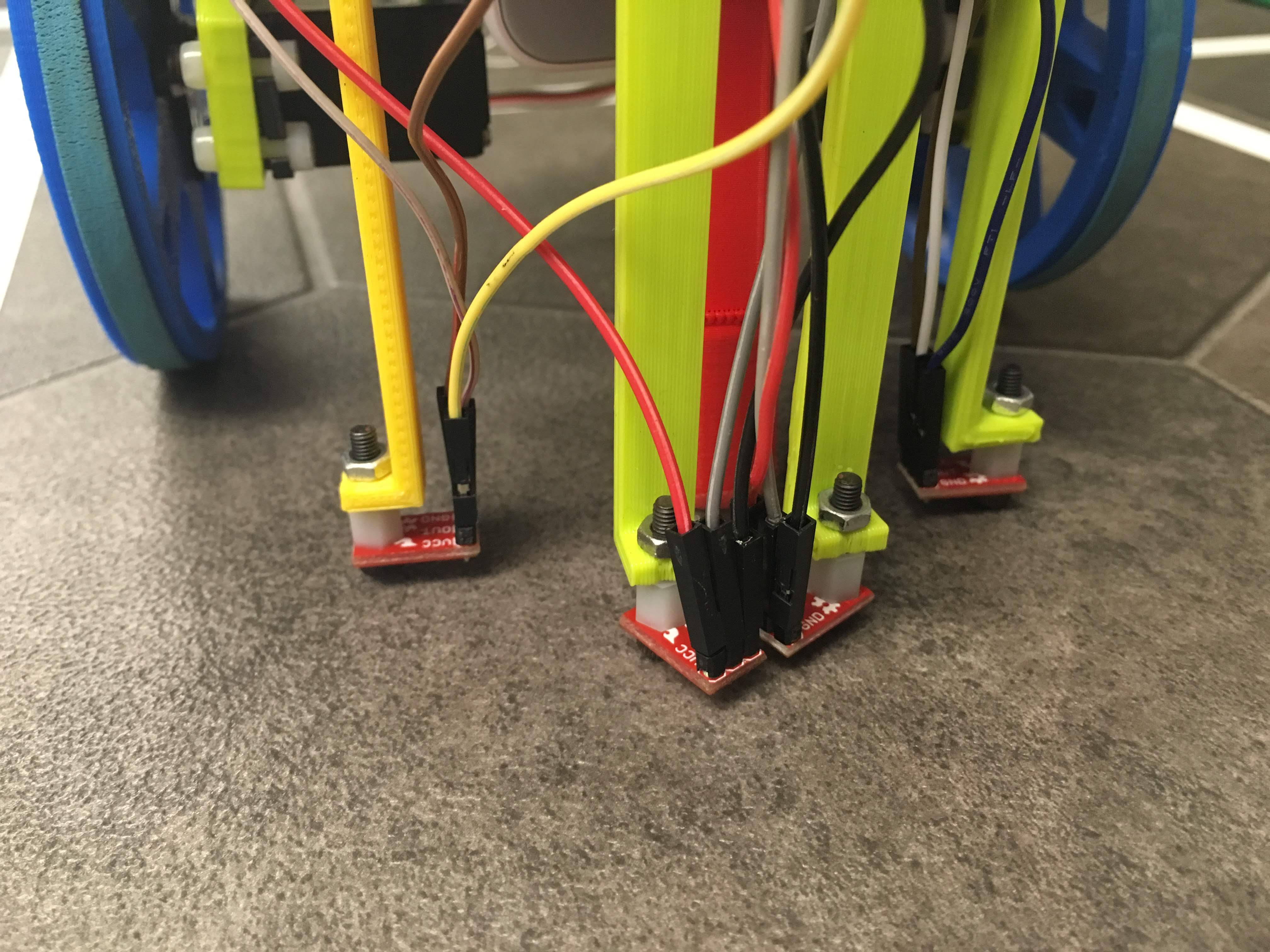
Below is the placement of the line sensors on our robot:
We initially had only three line sensors - one at the front and two at the sides. We decided against this design because when our robot strayed from the line, we were unable to tell which direction it had strayed in. This made us unable to correct it. The addition of the second line sensor at the front fixed this problem because it allowed the robot to detect if it was straying in the direction of the sensor that was no longer seeing white.
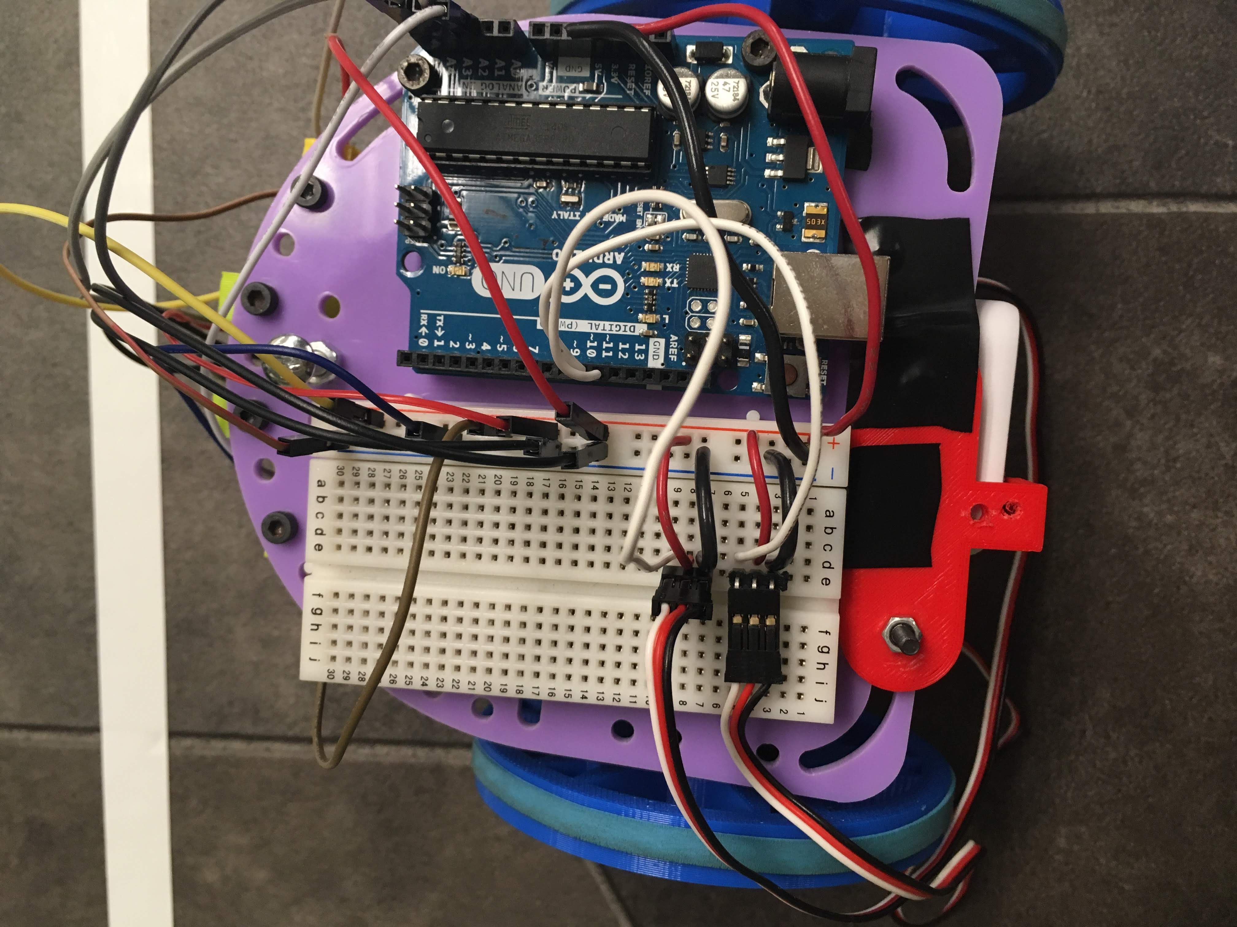
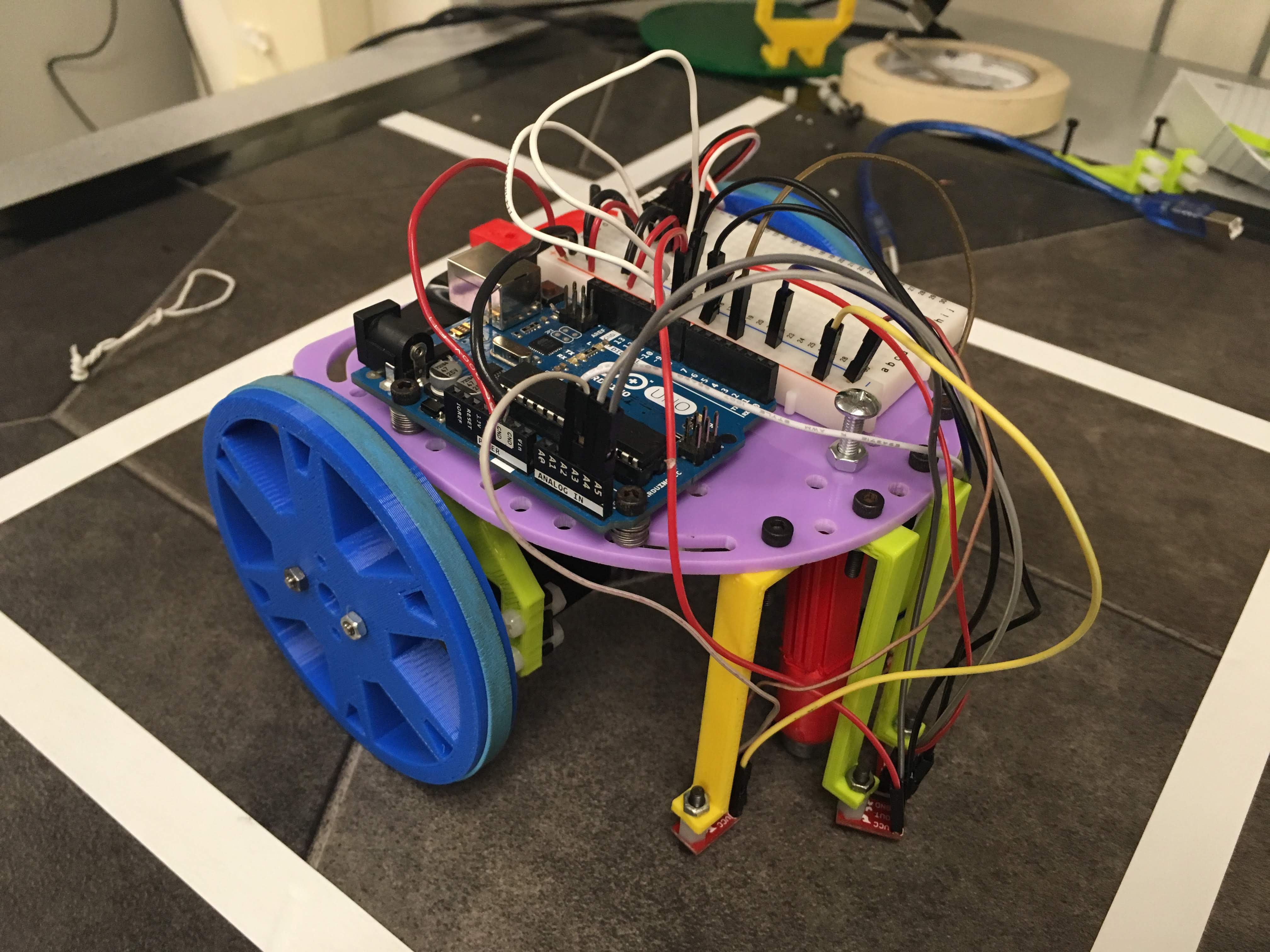
Aside from the sensors, we also changed the chassis that the hardware was sitting on. We placed the power source underneath the chassis, while the breadboard and the arduino sat on top. This allows for more room for wiring and potential growth of the robot as we move farther into its development.
Below are photos of our total robot:
Coding its Movements
Turning the Wheels
For sake of brevity, the pre-setup() and setup() code will be left out.
We have set up two wheels attached to the servos——leftWheel and rightWheel——which can both be written to with values from 0-180. We also have labeled our four sensors as frontLeft, frontRight, backLeft, and backRight. The “front” sensors (the two sensors placed on the white line currently being traversed) are designated strictly for line-following, while the “rear” sensors (the two sensors at 90 degrees to the "front" sensors) are for detecting an intersection.
The above code snippet demonstrates how we write the raw 0-180 values to the left or right wheels (servos). We’ve included “stop” functions to make stopping each wheel easier than writing 90 every time we want to stop it. For moving otherwise, we may want to vary the speed, so we leave a speed parameter in the top two write functions; these two functions are used in the following functions to make our robot execute various maneuvers.
// Forward, reverse, and turns. --------------------------------------------------voidforward()
{
writeLeft(speedLeftForward);
writeRight(speedRightForward);
}
voidreverse()
{
writeLeft(speedLeftBackward);
writeRight(speedRightBackward);
}
voidturnRight(int ms)
{
writeLeft(speedLeftForward);
stopRight();
delay(ms); // ms is in milliseconds!
}
voidturnLeft(int ms)
{
writeRight(speedRightForward);
stopLeft();
delay(ms); // ms is in milliseconds!
}
First, note the forward() function, which has changed slightly since lab 1! We abolished the move< left_or_right >Wheel< Anticlockwise_or_clockwise >() coding scheme. Instead, we simply write to each wheel a particular “speed-forward” integer, an integer from 0-180, which is defined in the pre-setup code but is not shown here. speedLeftForward is defined as a value above 90 because these values make the servo spin counterclockwise, and the left wheel needs to spin counterclockwise in order to go forward. Conversely (and simultaneously), the right wheel must spin clockwise in order for the robot to move forward, and so speedRightForward must be below 90! Let’s say speedLeftForward is defined as 120 (90+30); we must define speedRightForward as 60 (90-30) so that the servos spin at the same speed but in the correct direction depending on what side of the robot it is on. So, this new coding scheme allows more flexibility with wheel speed but requires that we remember what integer (0-180) that we must write to each wheel.
Now, examine the turnRight(int ms) function. To perform a right turn, the left wheel must be spinning faster than the right wheel, so we write to the left wheel a given speed and stop the right wheel from spinning. The parameter int ms allows us to calibrate how long we want our turn to take, by varying the time of the delay in milliseconds! This allowed us to calibrate our turns to be as close to 90-degree turns as possible, by varying the turn-time in milliseconds. We will replace this method of turn calibration, however, with a more robust solution that will be described later.
// Line-following procedures. ------------------------------------------------------boolisWhite(int pin)
{
int val = analogRead(pin);
return val > threshold ?false:true;
}
voidfollowLine()
{
while(!(isWhite(backLeft) && isWhite(backRight)))
{
if(isWhite(frontLeft) && isWhite(frontRight)) // if both sensors detect white, move forward regularly.
{
forward();
}
elseif(!isWhite(frontLeft) && isWhite(frontRight)) // if Left sensor detects black (if it veers left)
{
writeLeft(speedLeftForward); // keep Left wheel moving.
stopRight(); // stop the Right wheel.
}
elseif(isWhite(frontLeft) &&!isWhite(frontRight)) // if Right sensor detects black (if it veers right)
{
writeRight(speedRightForward); // keep Right wheel moving.
stopLeft(); // stop the Left wheel.
}
else
{
stopLeft();
stopRight();
}
}
}
Moving in a Line
Now, for the meat and potatoes; the line-following function!
First, we created a helper-function bool isWhite(int pin). We pass in an integer that represents the pin number of one of the four sensors (frontLeft, backRight, etc.), and if it’s read value is greater than the threshold value, then isWhite outputs false, otherwise it outputs true.
Within the function linefollow() is a while loop, whose condition basically reads as “while the ‘rear’ sensors read ‘notWhite’”, or in more perfect English, “while the robot is NOT at an intersection”. Once the robot reaches an intersection, we want the robot to execute a turn instead of the line-following function. To keep the robot straight, we use several conditionals that read like this:
If both sensors read ‘white’, then continue forward like normal.
If the LEFT sensor reads “black” (i.e. if it veers left), then spin the left wheel at normal speed and stop the right wheel (i.e. turn right).
If the RIGHT sensor reeads “black”, then spin the right wheel and stop the left wheel (veer left).
Finally, if neither front sensor reads white, then the robot stops.
Below is a video showing our robot moving along a white line using these conditions to reorient itself:
Making a Figure Eight
The final code snippet is a simple implementation of driving in a figure-eight pattern, which relied on the line following functions defined above. If the robot is placed in the middle segment of the figure eight, it takes four consecutive right turns followed by four consecutive left turns (or vice versa) to complete the figure eight and finish where it started.
Execute a figure eight whenever an intersection is detected.
Start the robot in the MIDDLE SEGMENT of the figure eight.
for(int i =0; i <8; i++)
{
followLine();
if(i <4) turnRight(1000);
elseturnLeft(1000);
}
This code successfully allowed our robot to traverse the grid in a figure-eight pattern, as shown in the video below:
Road Bumps
We have used two line sensors in the front and two sensors at the sides, to make the robot follow a line and turn, respectively. The front sensors work on the principle that if either one detects black, while following the white line, then it moves on the opposite direction of the detecting-sensor to maintain alignment. In other words, if our robot starts getting away from the white line, let's just say towards left of the white line, then our front-left sensor will start detecting black. This will make the robot go right, as it's coded to align itself that way. Hence, it will continue to stay on the white line.
Though this hardware and software design is effective in ensuring that the robot stays on its line, it led to issues with the motion of the robot itself. If the distance between the front sensors is nearly same as the width of the white line, then the robot will keep going left and right, in a forward manner. What it means is that the robot will move forward by following the white line but in a jittery fashion. This jittery nature becomes noisy and irregular if the speed of robot is increased.
Below is a video showing our robot moving along a line, but with jittery movements:
This was also noted when the robot moved in a figure eight:
There are two simple solutions to this problem: reducing the speed of the robot or trying to reduce the distance between the front sensors as much as possible. Although the former solution works, it is not an optimal solution——it is more of a prevention method than a solution. The latter was found to be a viable solution and ultimately effective solution. We reduced the distance between sensors and it was found that the jittery nature was reduced to an acceptable level.
Future Features
More Effective Turning
For turning the robot left and right, we fixed the speed of the robot to a particular value (assume it to be X) and then we hardcoded a count (assume it to be Y) to turn the wheels, so that we can make a clean turn. For example, let's say if we want to turn left, then we make the left wheel stop and make the right wheel rotate for Y counts.
Although the hardcoded value currently works, it may not if we change the speed to another value, Z. The value for rotation (Y) would increase or decrease, depending on whether Z < X or Z > X, respectively. The issue is that whenever we change the speed of the robot then we had to re-calibrate the turn-count.
This issue would be resolved if we designed the robo into a self-calibrating module, wherein it calibrate its turn as per the speed it runs on. How would we do that? The turns are done with a count to let the Arduino know for how many milliseconds it has to turn. Once the robot reaches an intersection, all four sensors will be on white. The robot can turn, either left or right, for an undetermined length of time——instead, it will wait to stop turning once the front sensors have reached white again. At that point, the turn will be complete, as the robot will have started on a white line, begun turning left or right, and then will have completed its turn on the next white line (90 degrees from the starting line). This ensures that differences in robot speed, or even inconsistencies in the grid squares, won't affect the ability for the robot to turn effectively.
Variable Line Sensing
Line sensor values are judged on the basis of a range from 0 to 1023 to differentiate between the reflectivity of IR light from various colors, specifically black and white for our project and lab work.
Line sensor values vary with respect to distance between the sensor and the ground (ground being the maze containing black and white regions), and also with respect to the light under which the robot is working (i.e. natural sunlight vs artificial light). The latter means that the read value changes in magnitude when the room is darker or brighter. There becomes a possibility wherein a robot might not be able to judge the color using the hardcoded range due to a drastic change in the environment's lighting.
To prevent this from becoming an issue, we can make the robot calibrate itself at the beginning of the course and get its readings of the ranges attributed to black and white. Since we have the initial placement of the robot within our control, we can ensure the robot sits on a white line (with the front two sensors as within the boundaries of the white line as possible) to start with. We can adjust the setup() function to read the value from the line sensor as it's above a white. Based on this value we can store a range (with some offset to incorporate any outliers) and use that range to differentiate between black and white.