After building multiple circuits throughout the previous labs and milestones, this milestone was meant to serve as the glue for all of them. Line follow, IR detection, and general robot structure were all relied on when developing the foundation for the robot's function and logic.
Procedure
Since there were so many parts to this lab, we had to split up and focus on the multiple aspects of work to be done. We all contributed to each part, but Orrin worked more on redesigning the robot, Luke worked more on the IR detection, Caitlin worked more on the wall detection, and Orby and Labhansh worked more on the overall structure of the FSM.
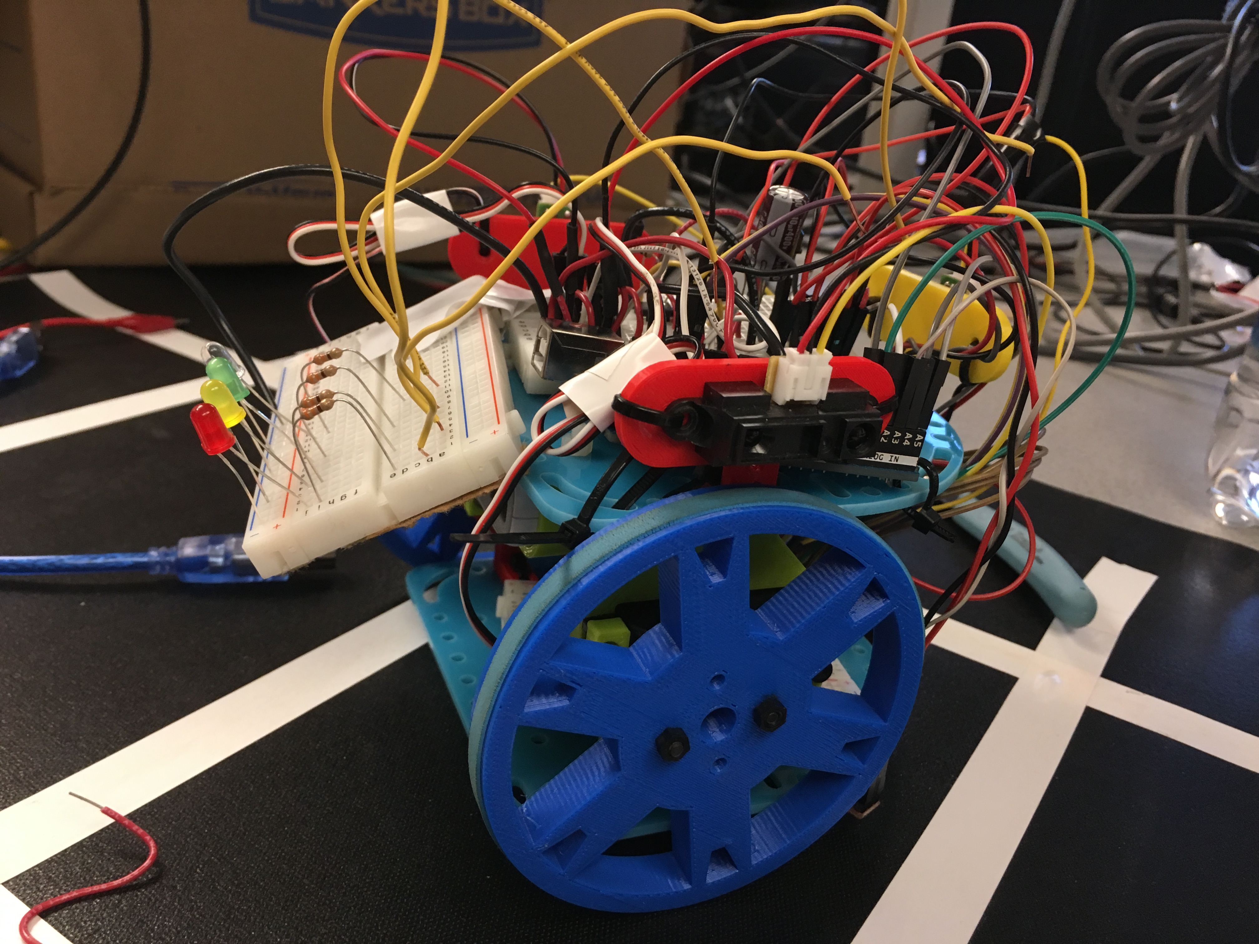
In terms of the hardware used in this milestone, there was the need to secure the phototransistor circuit from lab 2 to the chassis, as well as new short-range IR sensors for the wall-detection.
We realized that our robot was running out of space for all the hardware we needed to run the servos, the IR hat, the IR sensors, and the audio sensors. We redesigned our robot to have a chassis close to the ground, and servos fastened in the middle of the supports between the lower and upper chassis. We used mostly zip ties for most joints and for connecting components, primarily because they make it easy to quickly re-design and move parts around. Although the line sensors remained in the same general location on the robot, it is now jerky when it follows lines in the maze. However, this is likely due to a weight imbalance.
We also added the wall IR sensors on the front, right, and left of the top chassis, tied down with zip ties.
The functionality of the phototransistor is explained in full in lab 2 but to recap, it's a composed of a phototransistor circuit connected to a non-inverting amplifier. This is to ensure that any IR detected from the "hats" placed on robots can be read from farther distances, which will prove useful as the maze expands in competition.
The short-range IR sensors used for wall detection were new, and so we have to determine their functionality. The sensor uses IR signals to determine the physical presence of an object in front of it within a range of approximately 4-30 centimeters. The distance is outputted as a number threshold via an analog output. Three wall sensors were added so as to detect walls in front, to the left of, and to the right of our robot. Since there weren't any analog pins to spare for each of these sensors, they were fed into a mux with a digital output. This allowed us to provide the mux with select bits, choose one of the wall sensors to read from, and get the output through a digital pin (of which we have plenty of).
The code for reading the front wall through the mux is seen below. It's similar in logic to the other two walls.
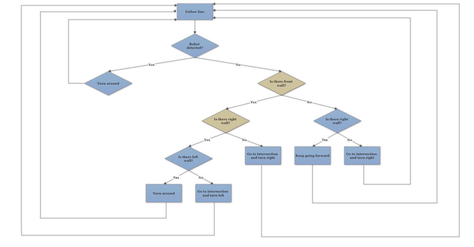
In order to implement a wall detection algorithm, we added three distance sensors to our robot. We only had one analogue pin left so we read outputs from the sensors using a multiplexer. We included one sensor for each wall we wanted to be able to detect i.e one for front walls, one for left walls and one for right walls. Then we checked the threshold values for each sensor by reading the output from the serial monitor when a wall was placed at a reasonable distance away from the robot. We drew the following flow diagram in order to better help us implement our algorithm.
In implementing this in the form of code, we created a state machine with three states: FOLLOW_LINE, ROBOT_DETECTED and FOLLOW_WALL. State FOLLOW_LINE was our default state and it basically checked if a robot was detected or not. If the robot was detected, the state machine moves to state ROBOT_DETECTED which makes the robot turn around and then Changes the state to state FOLLOW_LINE. However, if no robot is detected, the state machine moves to state FOLLOW_WALL which does all the wall detection. The code is as follows:
voidloop() {
state = FOLLOW_LINE;
while(1){
switch(state){
case FOLLOW_LINE:{
followLine();
if(robotDetected()){
state = ROBOT_DETECTED;
}
else{
state = FOLLOW_WALL;
}
break;
}
case ROBOT_DETECTED:{
turnAround();
state = FOLLOW_LINE;
break;
}
case FOLLOW_WALL:{
if (frontWall()) {
if (rightWall()) {
if (leftWall()) {
//Serial.println("turning around");
turnAround();
}
else {
goToIntersection();
//Serial.println("turning left");
turnLeft();
}
}
else {
goToIntersection();
turnRight();
}
}
else {
if (rightWall()) {
goToIntersection();
}
else {
goToIntersection();
turnRight();
}
}
state = FOLLOW_LINE;
break;
}
}
}
}
This was all put together into a program where Arnold successfully navigated a maze via right hand wall following.
Avoiding Robots
We Have to Play Nicely
To merge our Optical detection code into the state machine (wall-detection) code as described above, we used a similar approach as to when we merged the optical and acoustic programs for lab 2! All we had to do, in short, was to save several register values at the beginning of our function that would run the FFT, execute the FFT (Optical detection) code, and then restore the old values after the FFT is completed. If we hadn’t adjusted these register values (TIMSK0, ADCSRA, ADMUX, and DIDR0) before and after running the FFT, the servos would not run correctly (a common problem among teams) because the Servo and FFT libraries both use the same default timer. Instead of rewriting one of those libraries, we simply cached these register values: and it works!
Below is a snippet of our optical-detection function, robotDetected():
boolrobotDetected() {
bool retVal =false;
// Store old values
old_TIMSK0 = TIMSK0;
old_ADCSRA = ADCSRA;
old_ADMUX = ADMUX;
old_DIDR0 = DIDR0;
//Setup
TIMSK0 =0; // turn off timer0 for lower jitter
ADCSRA =0xe5; // set the adc to free running mode
ADMUX =0x40; // use adc0
DIDR0 =0x01; // turn off the digital input for adc0// Check
cli(); // UDRE interrupt slows this way down on arduino1.0for (int i =0 ; i <512 ; i +=2) { // save 256 samples while(!(ADCSRA &0x10)); // wait for adc to be ready
ADCSRA =0xf5; // restart adc
byte m = ADCL; // fetch adc data
byte j = ADCH;
int k = (j <<8) | m; // form into an int
k -=0x0200; // form into a signed int
k <<=6; // form into a 16b signed int
fft_input[i] = k; // put real data into even bins
fft_input[i+1] =0; // set odd bins to 0
}
fft_window(); // window the data for better frequency response
fft_reorder(); // reorder the data before doing the fft
fft_run(); // process the data in the fft
fft_mag_log(); // take the output of the fft
sei();
if ((fft_log_out[43] >=120) || (fft_log_out[44] >=120)) {
digitalWrite(3, HIGH);
//Serial.println("YES");
retVal =true;
}
else digitalWrite(3, LOW);
// Restore old values
TIMSK0 = old_TIMSK0;
ADCSRA = old_ADCSRA;
ADMUX = old_ADMUX;
DIDR0 = old_DIDR0;
return retVal;
}
Again, note how the four register values are stored as “old” at the beginning, and then restored at the end of the function.
As of now, our function simply returns true if IR is detected, and false if not. Our phototransistor is currently sticking straight up on our robot; so, this means that if essentially any IR hat is emitting IR anywhere near our robot, robotDetected() will output true. And when this function does output true, as per the state machine, at the next intersection our robot arrives at, it will make a U-turn (written in function turnAround().).
Although this is probably not desired/practical in the final competition, it allowed us to test our circuitry and software integration at a basic level. In other words, in the future we will move our phototransistor to the front of the robot (pointing forward), so that we know robotDetected()only outputs true if a robot is in front of it.
Successful robot detection (IR detection) is shown in the final video, where both IR detection and successful maze navigation are demonstrated.
The Final Outcome
It All Came Together!
Below, see our final iteration of Arnold in action! Watch as he navigates a maze (right-wall-following) in the first half of the video. In the second half, an IR hat is turned on in his vicinity (at a distance that is extremely close, mainly for the sake of recording the video), and, as expected, he U-turns at each intersection the IR hat is on!
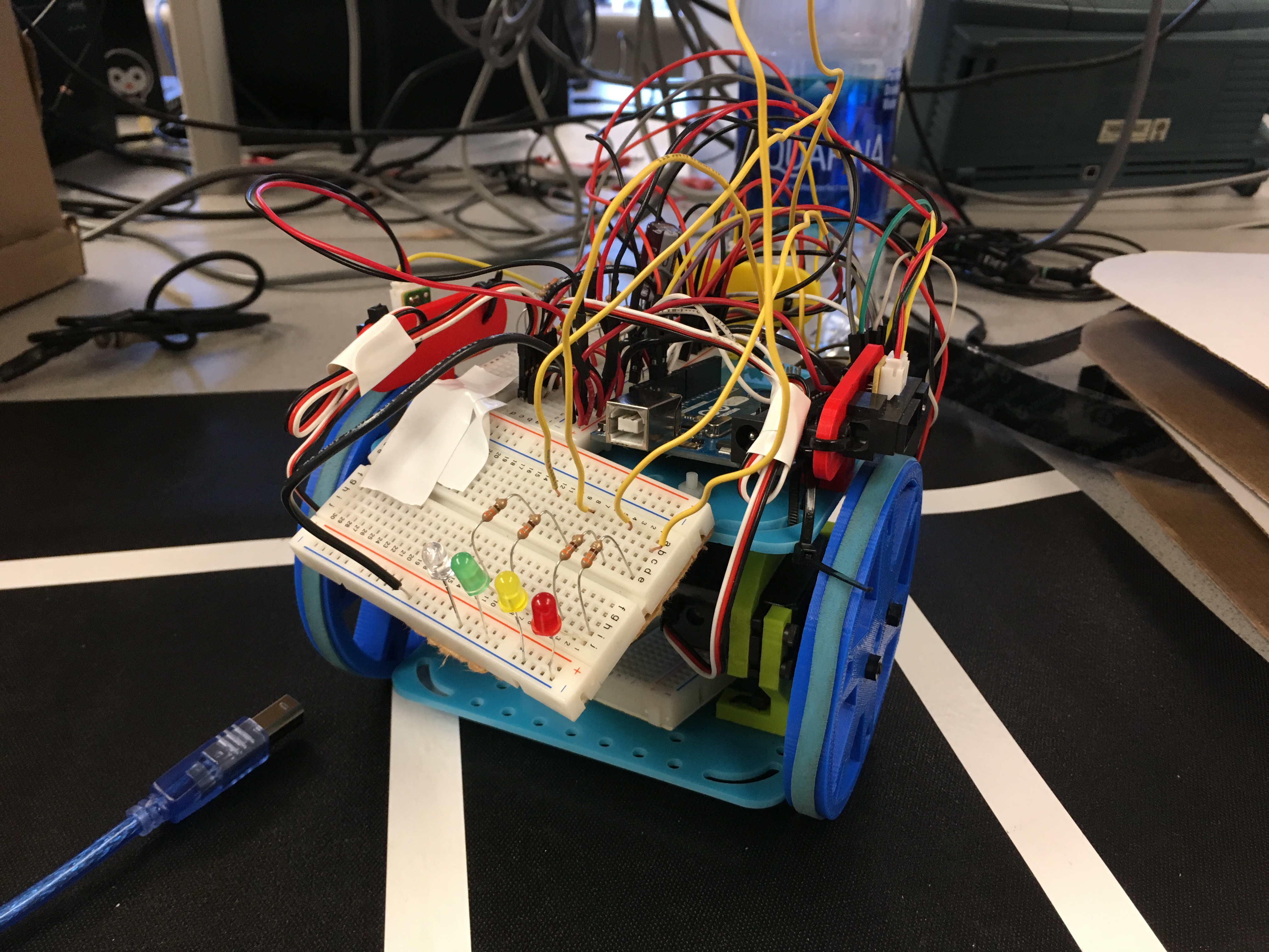
Notice our LED circuit on the back of Arnold:
There are four LED indicators in this circuit. The left-most white-colored (but actually red-light-emitting) LED lights up whenever robotDetected() = true. The other three LEDs, from left to right (Green, Yellow, Red) indicate whether a Left, Front, or Right wall,respectively, is detected. For example, notice when Arnold must U-Turn, all three of these wall-LEDs are lit up!
As mentioned earlier, some future improvements that we may make include:
Moving the current phototransistor to the front (for frontal robot-detection)
Adding more phototransistors for advanced robot-detection capability
Soldering our current circuits into protoboards (or print PCBs)
If we add more phototransistors (for the left and right sides of Arnold), we will need to update the robot-detection software to account for such sensor readings and make a more intelligent decision (which way to turn) based on its detection of other robots.
As the robot is increasing in size and functionality, the circuits on breadboards are getting hard to manage. Either soldering into protoboards or printing PCBs will save weight and space on our robot (we will need to add an FPGA amongst other components soon) and will enable us to reconfigure/relocate items easily.
Road Blocks
We Overcame a Bunch
The servo and FFT libraries use the same timer, so both can interfere in the functioning of each other. Some proposed solutions included:
We can change the FFT library due to it's complexity, but we can easily rrite our own Servo library, using related datasheet.
We can cache the affected registers (like TIMSK0, ADCSRA, ADMUX, DIDR0) before performing the FFT operation and then restore the values of these registers after performing the FFT operation. This is done because we manipulate these registers in our code, for robot detection.
We as a team, decided to give with the latter, because that was a more trivial and time-saving solution. And it works! Tried and tested. In future, if we face problems in value inconsistencies then we might switch to the former solution. But so far this solution has been fruitful.
Another issue was choosing an appropriate range for wall sensors to detect walls at a distance.
Below is a video when our wall sensors weren't calibrated well, resulting in Arnold running into a wall :(
For now we have calibrated the robot to the values that work best with mazes present in the lab. Once, we get the exact specs (like how far are the walls) of the maze present in the competition then we will able to calibrate the wall sensors appropriately.
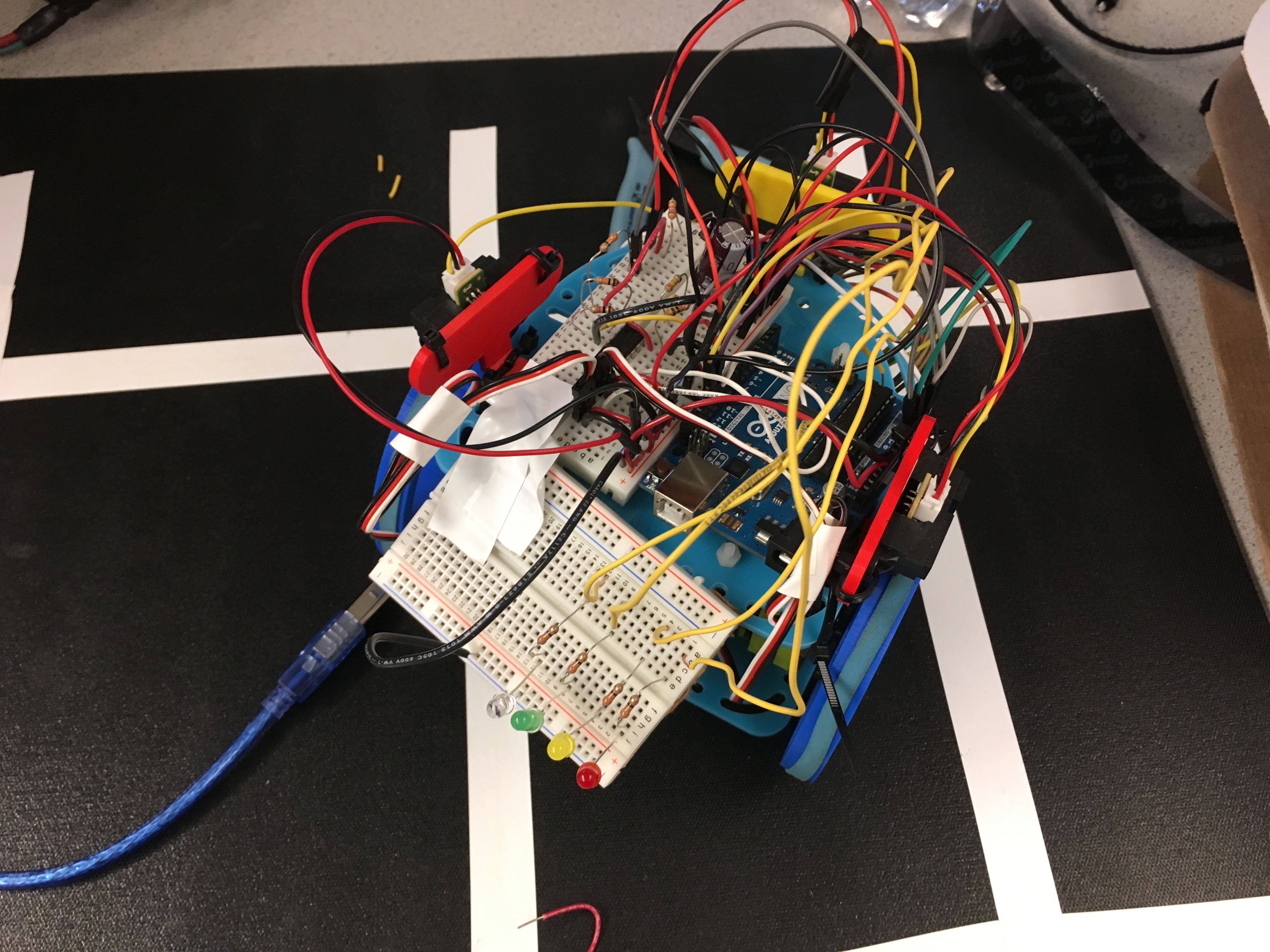
A roadblock that we'll most likely encounter in the future is the integration of various components together, specifically hardware. As the robot is increasing in size and functionality, the circuits on breadboards are getting hard to manage, as seen below:
Starting next milestone/lab, we are planning to use PCBs. Hence, circuit planning and designing is our next step.